Denver Metro/North Front Range 2017 Ozone Source Apportionment Modeling
Abstract
The Denver Metro/North Front Range Moderate Area Ozone State Implementation Plan (SIP) included 2017 ozone attainment demonstration modeling for the 2008 0.075 ppm ozone NAAQS. The attainment demonstration modeling used a 2011 CAMx modeling platform that was based on the Western Air Quality Study (WAQS) CAMx 2011b database available through the Intermountain West Data Warehouse (IWDW). Additional modeling was performed to look ahead to the new 2015 0.070 ppm ozone NAAQS. Local Source ozone source apportionment modeling was conducted to analyze ozone contributions from different source sectors within Colorado. The ozone source apportionment (SA) modeling results can be visualized using a web-based SA Vis Tool that is discussed in this wiki. The Denver ozone SIP modeling was conducted by Ramboll Environ and Alpine Geophysics under contract to the Denver Regional Air Quality Council (RAQC) along with the Colorado Department of Public Health and Environment (CDPHE) Air Pollution Control Division (APCD).
[http://views.cira.colostate.edu/tsdw/Tools/SourceApportionment_DenverLSA.aspx|LocalLocal Source Analysis SA Vis Tool]]Tool (*Note: it is best to use a browser other than Internet Explorer)
Overview
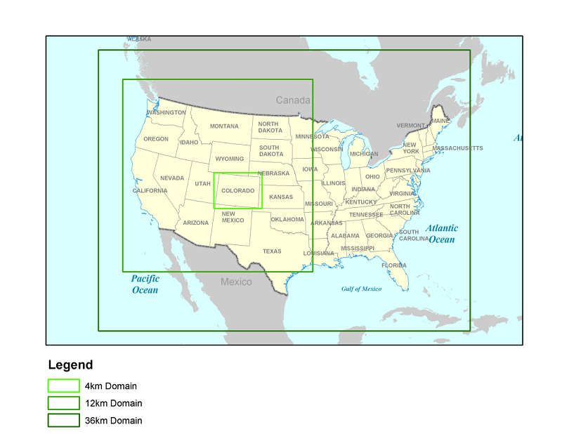
The Denver 2017 ozone source apportionment (SA) modeling was conducted using the Comprehensive Air-quality Model with extensions (CAMx) photochemical grid model (PGM) Anthropogenic Precursor Culpability Assessment (APCA) version of the Ozone Source Apportionment Technology (OSAT). Denver 2017 ozone SA modeling was conducted following the procedures in the March 21, 2016 SA Modeling Plan. The Local Source Analysis ozone SA modeling calculated the 2017 ozone contributions resulting from different source sectors in Colorado. The Denver ozone modeling used three domains as shown in Figure 1: (i) a Continental U.S. (CONUS) domain at 36 km grid resolution; (ii) a western U.S. (WESTUS) domain at 12 km grid resolution; and (iii) a Colorado domain at 4 km grid resolution. The Local Source Analysis ozone SA modeling was run on just the Colorado 4 km domain using boundary conditions (BCs) extracted from the 2017 CAMx 36/12 km CONUS/WESTUS domain simulation. Boundary Conditions (BCs) for the CONUS domain come from the MOZART Global Chemistry Model (GCM). A description of the CAMx OSAT/APCA ozone source apportionment tool is provided in Chapter 7 of the CAMx User’s Guide.
The Denver 2011 CAMx modeling platform was based on the CAMx 2011b 36/12/4 km modeling platform developed by the Western Air Quality Study (WAQS) and available on the Intermountain West Data Warehouse (IWDW). Details on the development of the WAQS CAMx 2011b modeling platform, including meteorological modeling and model performance evaluation (MPE), emissions modeling and the CAMx base case modeling, are available in reports on the IWDW. The Denver ozone modeling adopted the WAQS 36 km CONUS and 12 km WESTUS domains, but redefined the 4 km domain to focus on Colorado (Figures 1 and 2). The meteorological inputs for the Denver CAMx database used the same WAQS WRF 2011 36/12/4 km simulation output, but they were re-processed using the latest WRFCAMx processor (WRFCAMx v4.4 released April 2016). For the Denver CAMx 36/12 km domains, emissions from version 2 of the 2011 National Emissions Inventory (NEI) were used. For the 4 km Colorado domain, emissions were provided by the CDPHE/APCD. On-road mobile source emissions were based on the MOVES2014 on-road mobile source emissions model. For the Denver ozone Nonattainment Area (NAA), detailed link-based activity data were used based on Traffic Demand Model (TDM) output. More details on the Denver ozone SIP modeling database are provided in the Modeling Protocol, 2011 base case and model performance evaluation report and 2017 ozone projection modeling report.
Denver 2017 Local Source Analysis Ozone Source Apportionment Modeling
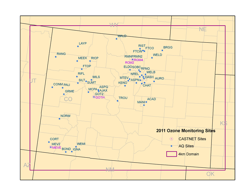
The Local Source Analysis ozone source apportionment modeling was conducted using the Denver 2017c CAMx modeling database for the Colorado 4 km domain and the May-August 2011 modeling period. Boundary Conditions (BCs) for the Colorado 4 km domain were based on the CAMx 2017c 36/12 km CONUS/WESTUS simulation. The Colorado 4 km modeling domain is shown in Figure 2. The Anthropogenic Precursor Culpability Assessment (APCA1) version of the CAMx Ozone Source Apportionment Technology (OSAT) was used. CAMx version v6.3 (released April 2016) was used in the Denver ozone SA modeling that has several updates to CAMx v6.1 (released April 2014) used in the WAQS modeling. One important update of CAMx v6.3 is the new OSAT/APCA source apportionment algorithms that track reactive nitrogen and odd oxygen through the chemical species; more details on the differences on the OSAT/APCA formulations are given in Section 7.1 of the CAMx v6.3 user’s guide.
Local Source Analysis Source Apportionment Groups
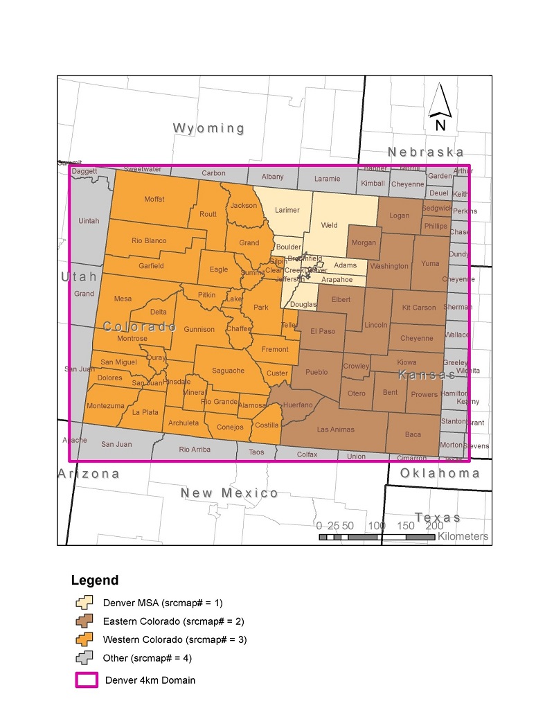
The Denver 2017 Local Source Analysis source apportionment modeling was configured to obtain ozone contributions from 4 Source Regions and 7 Source Categories. Separate ozone contributions were obtained for each Source Group that were defined as the intersection between the Source Regions and Source Categories. The Denver 2017 Local Source Analysis ozone source apportionment modeling used the following 4 Source Regions and 7 Source Categories;
Source Regions (Figure 3) (4)
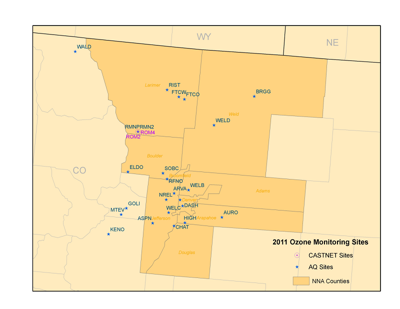
- 9 counties that are included in the DMA/NFR NAA (see Figure 4)2;
- Western Colorado;
- Eastern Colorado; and
- Slivers of Surrounding States
Source Categories (7)
- Natural Emissions (Biogenic, All Fires and Lightning NOX)
- Oil and Gas Emissions;
- On-Road Mobile;
- Non-Road Mobile;
- EGU Point;
- Non-EGU Point; and
- Remainder Anthropogenic.
With 4 Source Regions and 7 Source Categories, and the need to always include initial concentrations (IC) and Boundary Conditions (BCs) as their own separate Source Groups, that results in a total of 30 Source Groups for which separate ozone source contributions were obtained. The Western and Eastern Colorado Source Regions were defined as west and east of the Denver Metro/NFR NAA as shown in Figure 3. The use of separate Western and Eastern Colorado Source Regions will allow a better identification of the contributing sources. For example, the analysis separates the contributions from oil and gas emissions from the Denver-Julesburg Basin (east) versus the Piceance Basin (west). The CAMx 2017c 4 km Local Analysis Source Apportionment was conducted for May 1 through August 31 period using the 2011c 4 km WRF meteorology and 2017c base year emission inventory. Figure 4 displays the Denver Metro/NFR ozone NAA with locations of ozone monitoring sites where the results were analyzed.
Local Source Analysis Ozone Source Apportionment Modeling Results
The CAMx 2017c 4 km Local Source Analysis ozone source apportionment modeling results were summarized in a PowerPoint Presentation (PPT). The ozone contributions of each Source Group to the maximum daily 8-hour average (MDA8) ozone concentrations at each monitoring site within the Denver Metro/NFR NAA and vicinity for each day of the modeling period were extracted and loaded into a web-based source apportionment visualization tool (SA Vis Tool) that can be accessed here: Local Source Analysis SA Vis Tool
The SA Vis Tool generates pie charts of 2017 ozone contributions by Source Region, Source Category or both (i.e., Source Groups) for monitoring sites within the Colorado 4 km modeling domain. The use of the SA Vis Tool involves the following:
- Selection of whether ozone SA visualization is for monitors from the AQS or CASTNet monitoring networks.
- Select whether ozone at the monitor (Local) or maximum within 3x3 or 7x7 of a monitor in 2011 base case is desired.
- Selection of the monitor where data is requested. This request can be made by selecting the monitor from drop down menus for State, County and Site or by using the map and selecting the monitor location.
- Select the day where results are desired. The day can be selected from a top five ozone day list for that monitor, from a drop down menu of ranked ozone days from high to low during the May-Sep modeling period or from a calendar. Note that multiple days can also be selected and the SA Tool will visualize the average contribution across those days.
- The SA Vis Tool will then visualize the modeled 2017 MDA8 ozone value for the selected monitoring site and day:
- The top bar in the plot will list the modeled 2017 MDA8 ozone for the selected site/day(s), the amount the ozone is due to BCs around the 4 km Colorado domain (BC-4km) and the amount of the rest of the ozone (Non-BC);
- Initially, the upper pie chart will be the Non-BC ozone contributions by Source Regions;
- Initially, the lower pie chart will be the Non-BC ozone contributions by Source Categories;
- Next to the lower pie chart will be a 10-day time series centered on the day in question that shows total MDA8 ozone and ozone due to BC-4km;
- The monitoring site or day can be changed using drop down menus in the top left. The day can also be changed by clicking on the MDA8 ozone for a new day in the time series chart.
- The Region/Category pie charts can be switched.
- Clicking on one of the pie slices in the top pie chart provides more information in the bottom pie chart about that slice.
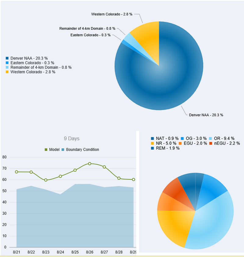
Figure 5 displays an example from the Local Source Analysis SA Vis Tool for 2017 ozone (Local) at the Chatfield monitoring site in Douglas County, Colorado based on August 26, 2011 meteorology. The total modeled 2017 MDA8 ozone is 74.2 of which 56.2 ppb (76%) is due to the BC-4km and the remaining 18.0 ppb (24%) non-BC portion is due to emissions in the Colorado 4 km domain. The pie charts show the contributions from the non-BC portion of the ozone with the percent numbers with the pie slices displaying the percent of total ozone (i.e., with the BC-4km contribution). For Figure 5, ozone from the Denver Metro/NFR NAA contributes 20.3% of the total ozone so since the non-BC portion of the ozone is 24% the NAA pie slice takes up 84% of the non-BC pie chart. In the lower Source Category pie chart the slice size is the fraction of the non-BC portion while the percent contributions are the contribution to the total ozone. The key to the definitions of the Local Source ozone SA modeling Source Contributions are as follows:
- NAT = Natural Emissions (Biogenic, Lightning NOx and Fires)
- OG = Oil and Gas Emissions
- OR = On-Road Mobile Source Emissions
- NR = Non-Road Mobile Source Emissions
- EGU = Electrical Generating Units Point Source Emissions
- nEGU = Non-EGU Point Source Emissions
- REM = Remainder Anthropogenic Emissions (Area Sources)
_____________________________________________________________
1APCA differs from the OSAT ozone source apportionment tool in that ozone is only allocated to Natural emissions when it is formed due to Natural NOx emissions interacting with Natural VOC emissions. For example, when ozone is formed due to the interaction of biogenic VOC with anthropogenic NOX emissions under VOC-limited ozone conditions, a condition where OSAT will assign the ozone formed to the biogenic VOC source category, APCA recognizes that biogenic VOC cannot be controlled so redirects the ozone formed to the anthropogenic NOX emissions category.
2The northern portions of Larimer and Weld Counties are not part of the Nonattainment Area, but segregating those areas the Source Region would have minimal impact on the Source Apportionment.